Using the LTC1298 or SP8538 A/D
Converters to Measure Voltage
Submitted by:
This application note details the use of the very popular LTC1298 12-bit
A/D converter IC. The LTC1298 is manufactured by Linear Technology Corp
but another version of this IC is Manufactured by SIPEX, inc. The SIPEX
part (SP8538) tends to be less costly and exhibits better performance in
differential mode. Protean Logic currently stocks a supply of the SP8538
if you have difficulty locating a source for this part.
There are two approaches to interfacing the LTC1298/SP8538. The first
approach uses general purpose pins to create the serial data and clock
signals required to read the voltage on the input pins of the A/D. The
second uses a section of hardware within the TICkit 62 called the Synchronis
Serial Port (SSP) and generates the same serial data and clock pattern
at a much faster rate.
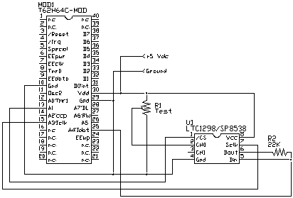
The software approach is the easiest to understand and this application
note deals with this method. The circuit for this program is shown below:

The program to read the voltage at pin 3 of the SP8538 is as follows
; program to read an LTC1298
DEF tic62_c
LIB fbasic.lib


DEF ltc_cs pin_a1
DEF ltc_clk pin_a3
DEF ltc_data pin_a4


LIB ltc1298.lib


FUNC none main
BEGIN
   rs_param_set( debug_pin )
   pin_high( ltc_cs )
   pin_low( ltc_clk )

   rep
      con_out( read_ltc1298( 1b ))
      con_out_char( 13b )
   loop
ENDFUN
The program above is incredibly simple since all of the difficult stuff
is performed by a call to the routine "read_ltc1298". This routine
is contained in a file called "ltc1298.lib" which is available
on the TICkit release disk. The library is shown below:
; Functions to control A/D
; These functions rely on three defines to work properly
;       cs   =  Chip Select pin    'Must have a separate line  '
;       clk  =  Clock control pin  'Can share a data line with other device '
;       data =  data pin           'Can share a data line I.E. a LCD'


; Routine to read a data from an LTC1298 or LTC1288 A/D chip

FUNC word read_ltc1298
    PARAM byte config           ; This value indicates mode and channel
                                ; for the A/D chip.
                                ; bit 7 = mode ( 0=single end, 1=differential)
                                ; bit 1-6 = channel select
                                ; bit 0 = polarity for differential or lsb
                                ;         channel select for single ended
    LOCAL byte count 0b
BEGIN
    pin_low( ltc_clk )
    pin_low( ltc_cs )
    pin_high( ltc_data )                ; start bit
    pulse_out_high( ltc_clk, 10w )
    IF b_and( config, 0y10000000b )       ; do we want a differential conversion
        pin_low( ltc_data )
    ELSE
        pin_high( ltc_data )
    ENDIF

    pulse_out_high( ltc_clk, 10w )
    IF b_and( config, 1b )                ; select channel or polarity
        pin_high( ltc_data )
    ELSE
        pin_low( ltc_data )
    ENDIF

    pulse_out_high( ltc_clk, 10w )
    pin_high( ltc_data )                ; use msb first format
    pin_high( ltc_clk )                 ; clock in the msbf bit
    =( count, pin_in( ltc_data ))       ; make data line an input
    pin_low( ltc_clk )                  ; return clock to low state

;    delay( 10w )                        ; settling delay

    =( count, 0b )
    =( exit_value, 0w )                 ; get data loop ready
    REP
        pulse_out_high( ltc_clk, 10w )  ; clock for next data bit
        =( exit_value, <<( exit_value )); shift exit word to the left
        IF pin_in( ltc_data )
            ++( exit_value )
        ENDIF

        ++( count )
    UNTIL ==( count, 12b )

    pin_high( ltc_cs )
ENDFUN
The byte value passed to the LTC determines which mode to use to read
the two input channels and which channel or differential polarity to convert.
The meanings of the parameter is as follows:
0x00b = Single Ended Conversion on Channel 0 (pin 2)
0x01b = Single Ended Conversion on Channel 1 (pin 3)
0x80b = Differential Conversion Channel 1 - Channel 0 (pin2 - pin3)
0x81b = Differential Conversion Channel 0 - Channel 1 (pin3 - pin2)
In the main program above we are converting the voltage on pin2 to a
number between 0 and 4095 where 0 is 0volts and 4095 is nominally 5 volts.
Protean Logic Inc. Copyright 05/06/04
Top of Page
